
By Bob Caletti
The restoration journey detailed in this article started when I saw an ad on the bulletin board at the MBSI convention a couple of years ago in Minnesota. Marty Persky was advertising a machine for sale listing it as a 27½-inch Symphonion “Project.” He had a picture of what a restored version should look like since he had recently sold one just like it to Jonathan White. I learned later that this particular machine is quite a rare model and the one Marty sold ended up being shipped to New Zealand. The fellow that Marty bought the “Project” Symphonion from had given up on restoring it. Since I am not one to shy away from a challenge, I decided to buy it. My wife, Judy, saw Marty shortly afterward and told him she forgives him for making her a Symphonion widow. She didn’t know how long it would be before she would see me again as I would be so focused on restoring this “Project.”
A few months after agreeing to purchase the machine, Marty was able to get it shipped to me in California from Chicago. It arrived on my birthday with all of the pieces packed inside the cases (top and bottom) plus an extra box or two. After unpacking the pieces, I laid them all out on my backyard patio to assess what I had and find out what might be missing. I find it’s always hard to really know exactly what parts are missing or wrong until you get into the restoration.
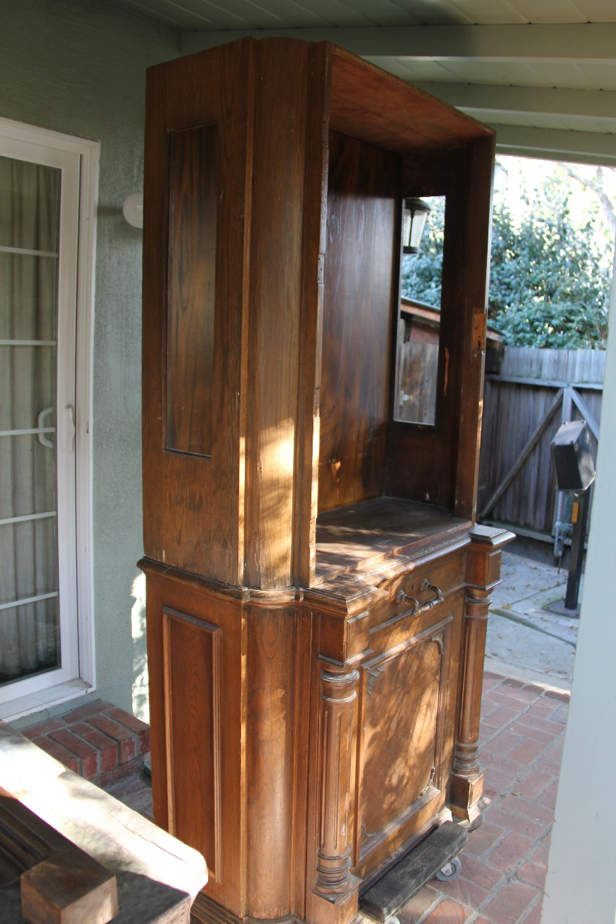
Symphonion upper and lower case as received from Marty Persky, most of the case needed re-veneering

A careful inventory of all of the parts was undertaken to determine which parts were missing and which ones were damaged and had to be remade. Restoration work was started from the bottom of the case and proceeded upwards to the top where the gallery was missing.

The bottom of the case section had to be completely disassembled and put back together as it was coming apart and was distorted.

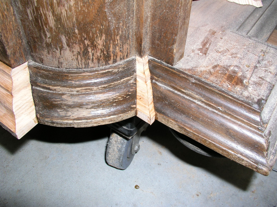
The bottom of the case showing missing moldings being fitted in, note double miters
This case was very fancy with a lot of interesting details. In order to make new versions of the missing molding pieces, a custom router bit had to be manufactured. To get the router bit I needed for this job made to the right specifications, I first had to send the router bit maker an accurate profile of the desired molding (see sidebar on how to do this). This profile was then drawn into a CAD (Computer Aided Drafting) file by the vendor and a scale copy of the drawing was printed and sent back to me for approval. I compared the paper drawing to the original molding and found that it matched up exactly, so I gave the bit maker the go ahead to make the custom router bit out of carbide. The bit is then braised onto the cutter body. When I received the bit, I got to work right away making new moldings out of solid oak.
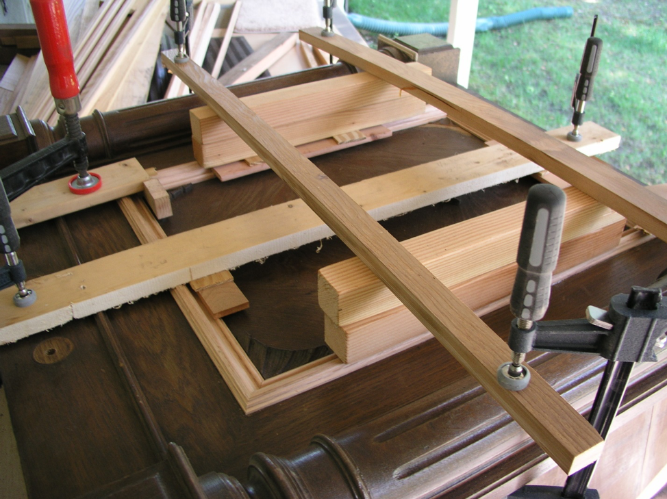
Another custom router bit had to be made to make the replacement molding on the bottom door. Part of the molding was original and part was a different molding that was pieced in, so we decided to make all new molding for this door panel.


Another custom router bit was ordered to make new molding for the upper top section. Molding was made using the router bit and a rotary table on the milling machine




MBSI members Jonathan White and Rod Cornelius from New Zealand both have 27½-inch Symphonions and were both very helpful in providing pictures and measurements to help me identify and make new parts to replace those that were missing. Most significantly, the entire gallery that sits on top of the machine was not present when I purchased the “Project.” Johnathan sent several images and a variety of different measurements to help make all new finial and gallery spools. Drawings were made for each of these parts and then they were made in oak using CNC machine turning. I am very grateful for Jonathan and Rod’s help. Without them, this machine may never have come back the way it has.


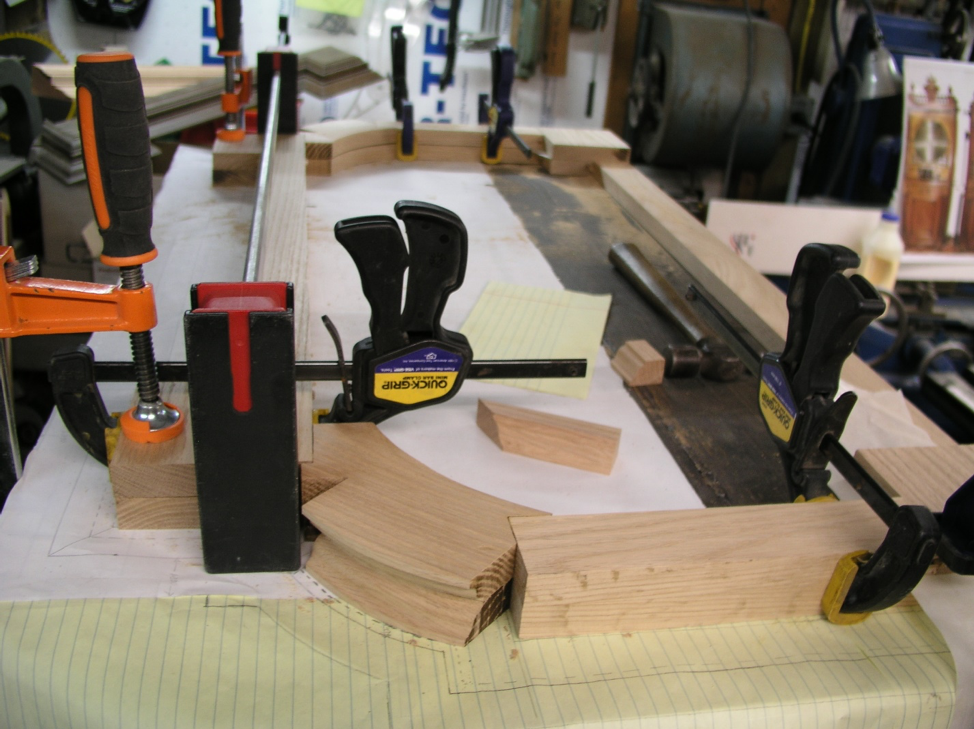
Top gallery was completely missing so a new one had to be designed and fabricated.


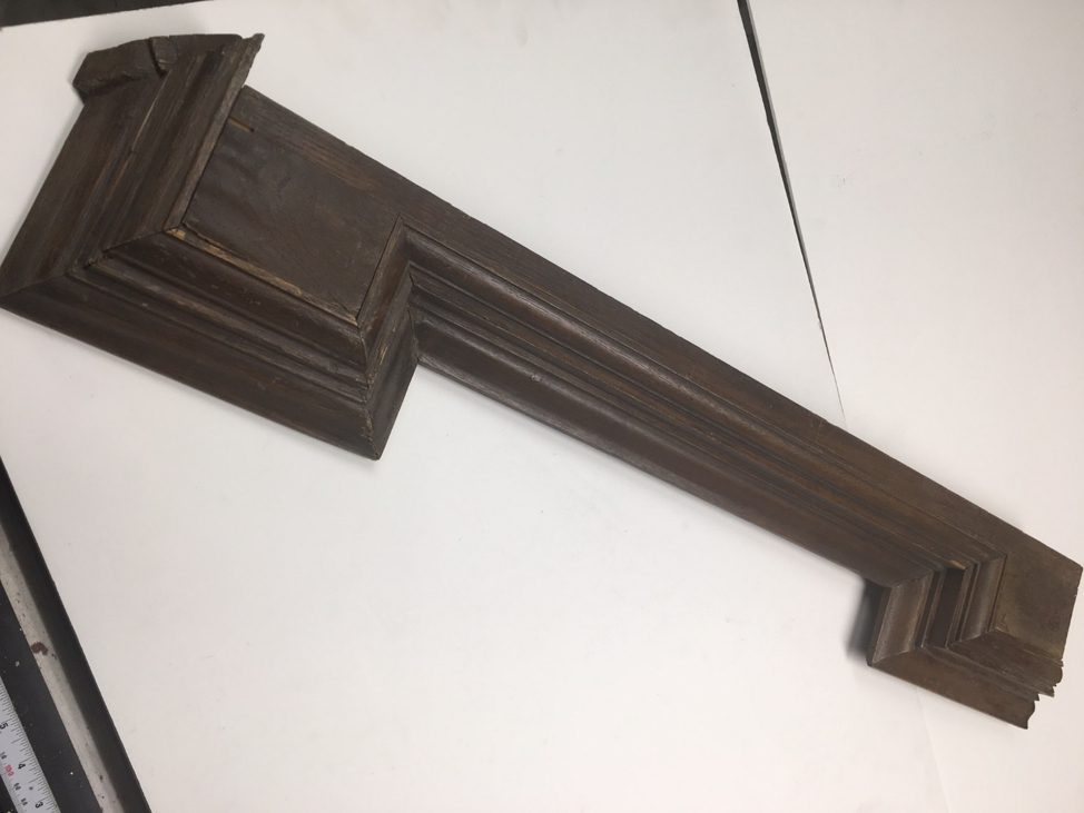
Gallery Center Pediment block picture from Jonathan White in New Zealand used to copy carving details.

With the aid of several pictures, some sets of dimensions and digital photo editing software Photoshop, I was able to create an actual size picture with correct proportions of the top carved crest. This photo was then used to mock up, cut out and drill a pattern that was then handed over to a woodcarver who created the final product.


Sound Board
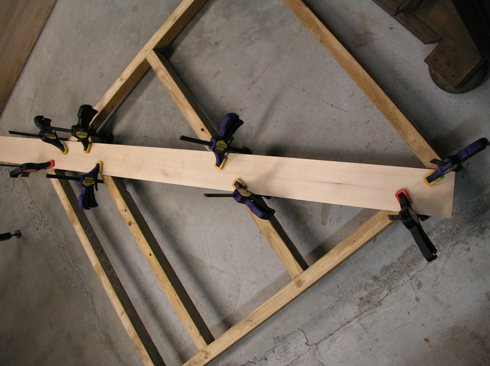


Disc support bracket

To make a missing disc support bracket I took a photo sent by Jonathan and scaled it to what I thought would be the correct size using Photoshop. Several attempts later, I had an actual size template which I could fit into the case in the position that the actual part would later fit into. The dimensions on this part are very critical and position sensitive. I followed the same process to get actual size photos of the door key and escutcheons.


These photos were then turned into 3D CAD drawings that were used to machine carve a wood pattern. The wood pattern was then used to make a sand casting. Then, finally, the brass casting was machined as needed. For the crank handle, a drawing was made of the wood handle and then it was CNC machine turned. The necessary added pieces were drawn up and machined to complete the handle assembly just like the original.
This completed the parts for the case and accessories. Now attention was turned to the music box mechanism.

Comb and bedplate as received-fortunately the combs had very little wear and only light surface rust.
Fitting Spring motor, bedplate and bell mechanism in restored case before case was refinished

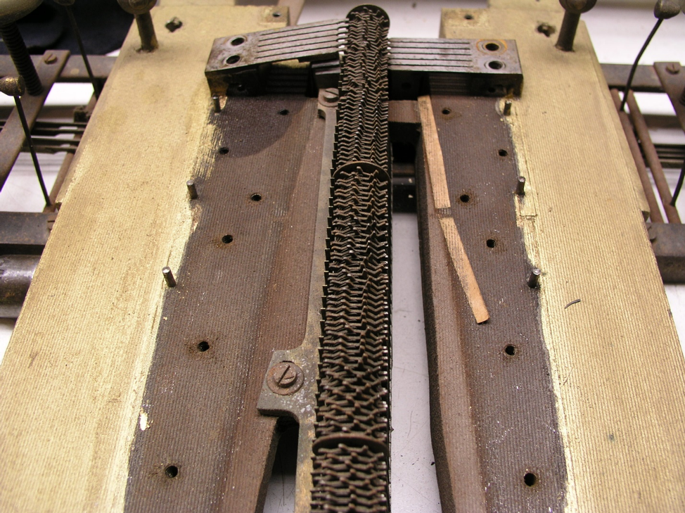

Care must be taken to identify where all the parts are located so that it can be put back the same way.
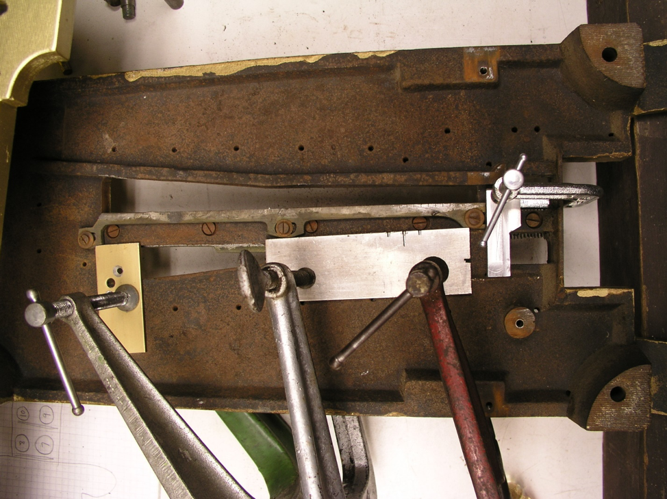
There were some bent and corroded star wheels that had to be removed for straightening and lapping. This meant that the damper rails and center post had to be removed so that the star wheels could be taken out and restored. Similar fixtures were used to remove the center post so that they both could be replaced back in exactly the same position. The damper rails and center post have a very critical alignments and need to be put back exactly where they were, this Is not a job for an amateur.


This mechanism is the dimple drive style from the German version of this music box, this same music box sold in the United States uses the conventional sprocket drive that interfaces with the holes in the perimeter of the disc.

Picture from Kevin McElhone showing a similar Symphonion with the door open and closed. This picture was the basis for the reverse gold leaf gilding I had done to the door glass
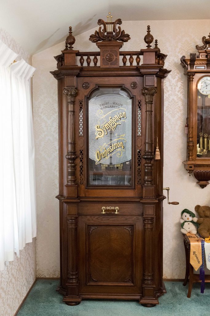
My completed 27 ½” Symphonion music box with 12 bells and gold leaf design on door glass. Note all glass is beveled
This music box stands almost 9 feet tall and took 1 ½ years to restore.

Symphonion with door open

Symphonion mechanism with motor cover removed-large view

Symphonion mechanism with motor cover removed with disc-close up

New 27 ½” discs were obtained from Lester Jones from the UK.
Credits:
The photo of another 27 ½” Symphonion is from Kevin McElhone’s book, The Disc Musical Box published by M.B.S.G.B has been used with permission from Kevin McElhone.
Thanks to my wife, Judy, for her support and encouragement through this whole project including giving up a dresser in our bedroom to make space for this very large music box.
Making custom router bits for producing moldings
There were a lot of missing and incorrect moldings on this case due to previous attempts at restoration. To replace these moldings required making custom router bits and making the moldings needed. The following text and pictures shows how that process it done.

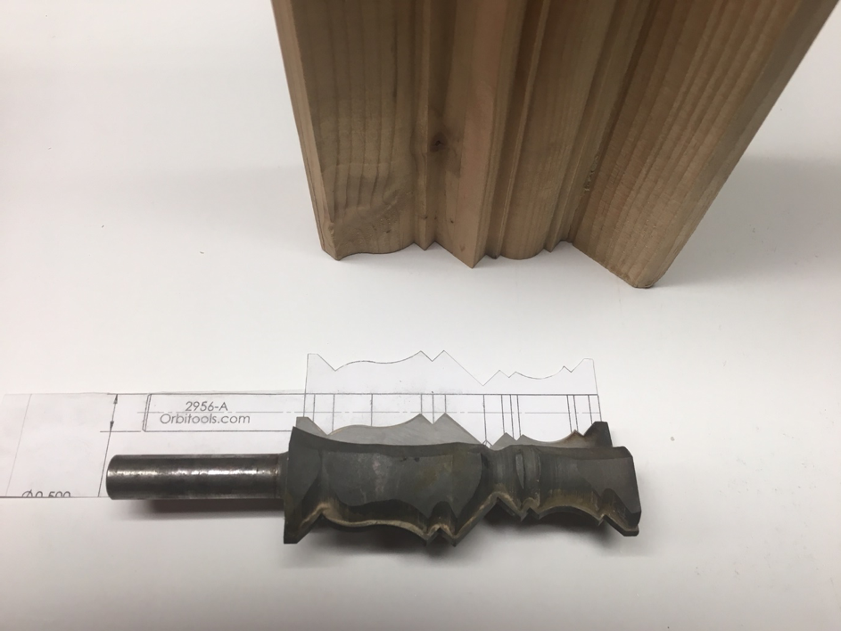
Molding profile is traced to size and sent to the custom router cutter maker. The people that make the router bits generate a CAD drawing that is to scale and send it back to me so I can compare it to the molding profile I have. If it is OK I let them know and they make up a carbide cutter like the one shown.

This molding will take 2 separate cutters and multiple passes to produce the profile shown.

How To Create A Mold Of A Sample That Can’t Be Cut
Mark Slabaugh, Orbit Tool Works
Here is how to make a cast of the existing shape. This works well if you cannot cut across section, and cannot photograph the cut directly.
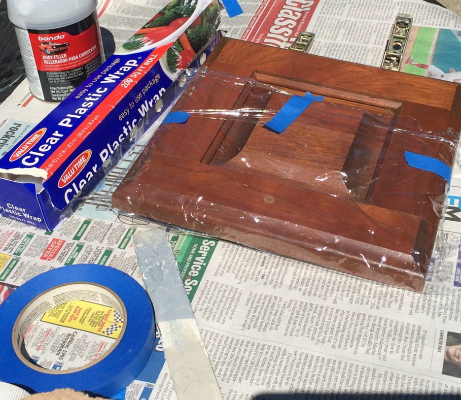
I find that bondo body filler works well when making a cast of the shape. You can purchase bondo at your local auto parts store. You will also need a mixing stick, plastic wrap and masking tape. Cover the part to be molded with plastic wrap and hold it in place with masking tape. Leave slack in the plastic so that the bondo can be pressed in.
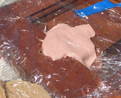
Mix the bondo, and fill the area to be molded. Place more plastic wrap over the bondo and press it into the cut.

The bondo will harden enough to handle in a few minutes. Remove it from the form and cut a cross section using a hacksaw. Sand or file the face to form a sharp edge on the bondo, and check the fit.


Scan the bondo shape with a scale and send the scan to us. Include pictures of the part you are replicating so that we can better match the shape. Notice that the bondo did not replicate the undercut well and we will need to make a correction during the next step.


When we receive the scan and pictures from you, we use them to create a scale drawing of the shape.

This trace of the shape is used to create the cutter drawings.
Dimensions are then added and the drawing is sent to the customer for approval.
These drawings are then used to create the CNC lathe program to cut and mill the body of the cutter. A steel blank is rough turned, and the shank is ground to size. The cuter body is turned to size on the lathe and the blade pockets are cut on a milling machine.
The drawings are used to create the CNC grinder program and the carbide blades are brazed on and the blades are ground to shape on the grinder.
The cutter is inspected, packed and shipped to the customer.
Mark Slabaugh
Orbit Tool Works
Felton, CA
www.orbittools.com
sales@orbittools.com
888-425-7130
- Photos of original machines/parts in New Zealand by Jonathan White and Rod Cornelius
- Restoration Photos by Bob Caletti and Jonathan Hoyt
- Woodwork mostly by Jonathan Hoyt
- Missing parts design/drawings by Bob Caletti
- Mechanism restoration by Bob Caletti and Jonathan Hoyt
- Photos of finished Music Box by Robert Thomas